10/30/50/100W LED application driver (UC3843A)
Table of Contents
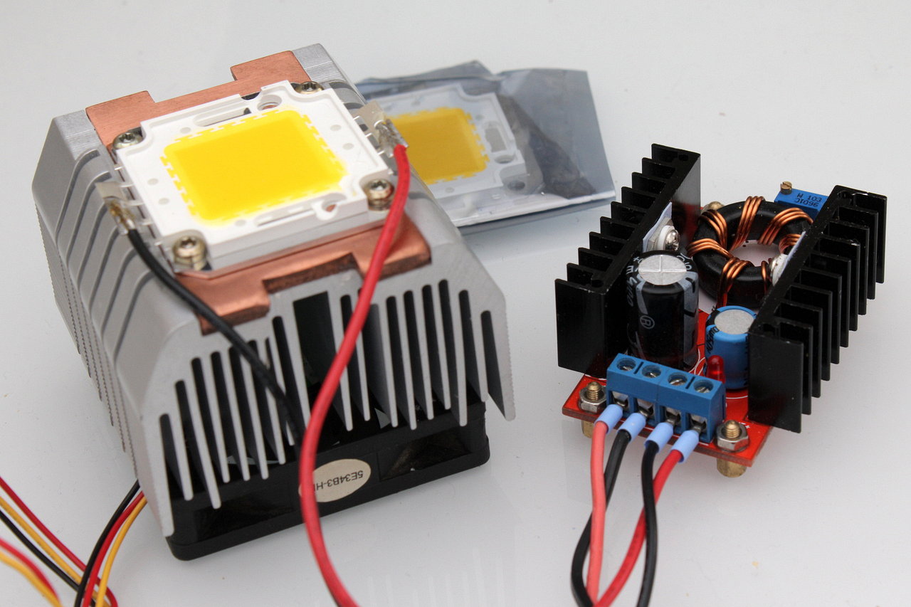
The operation of power LEDs calls for constant current source for higher performance. (> = 1A)
As an example, of operating a 30W was shown LED to a modified Step-Up Converter (boost) here.
One is to use 30W power led with the following parameters:
- Power: 30W
- Color temperature: 3000-3500 k
- Operating voltage: 30-38V
- Operating current: 1A
- Light output: 2600-2800 lumens
- Life duration: > 50,000 hours
On the laboratory power supply, the operating current of 1A at approx. 38V adjusts itself.
No constant current source is available, it can be operated LED with under voltage at low light output degradation. This voltage is selected, where the current is 10% less operating current (900mA). It is to make sure that the power, caused by thermal drift, specified does not exceed the operating current of the manufacturer.
Using a Step-Up transformer (boost), this led also to voltage sources can be operated, whose output voltage < = operating voltage is. (E.g. batteries, rechargeable batteries, power supplies)
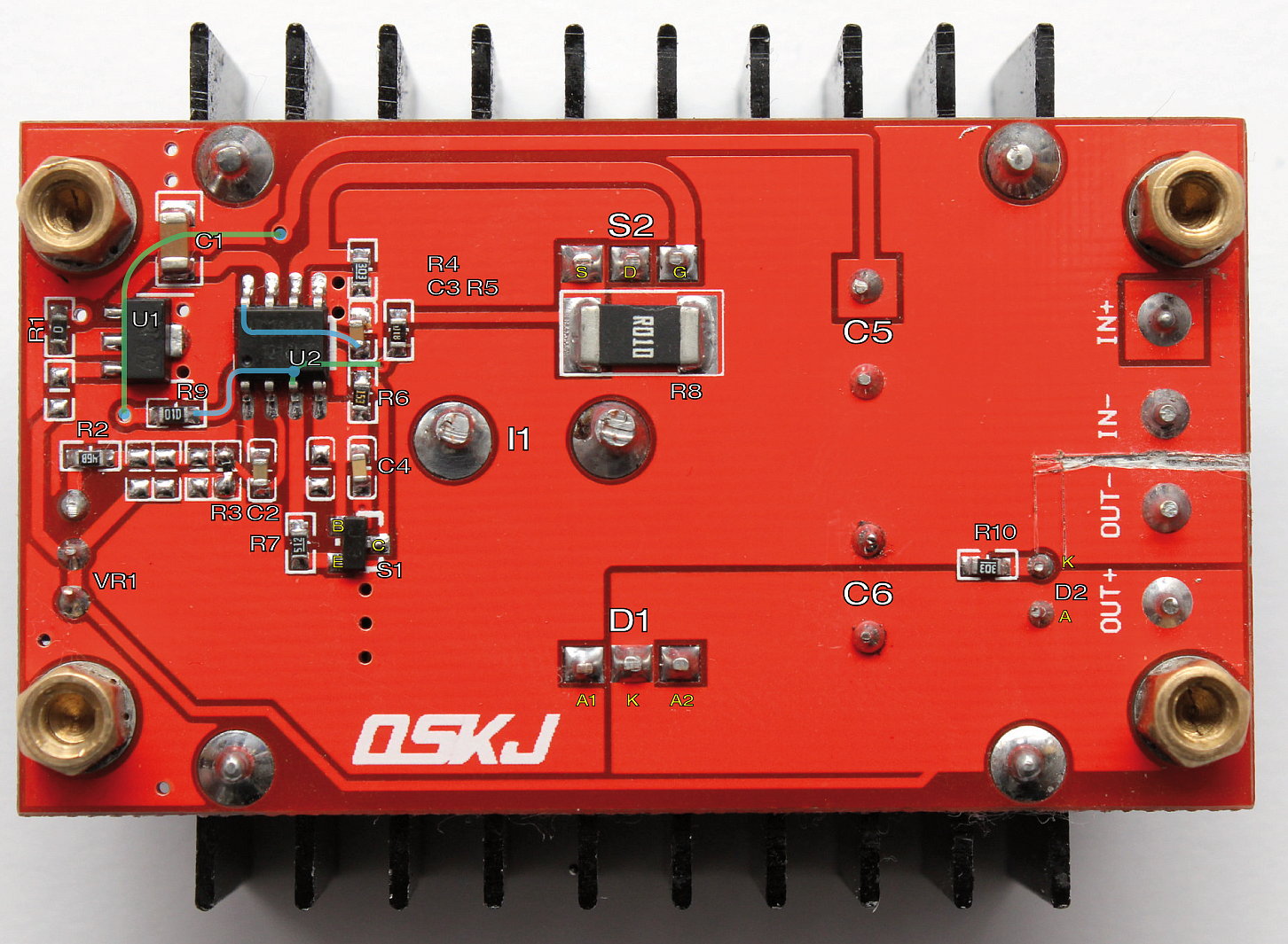
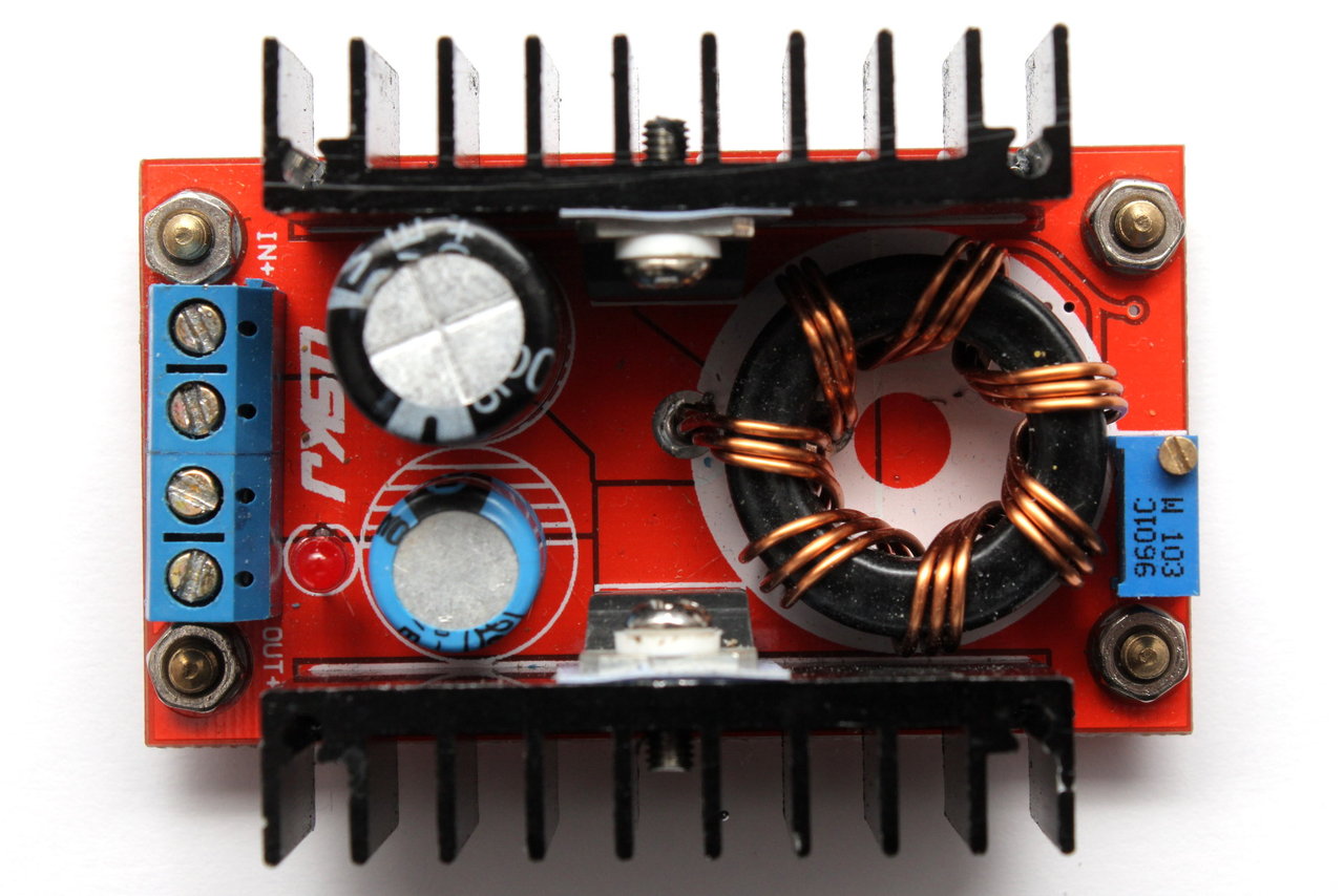
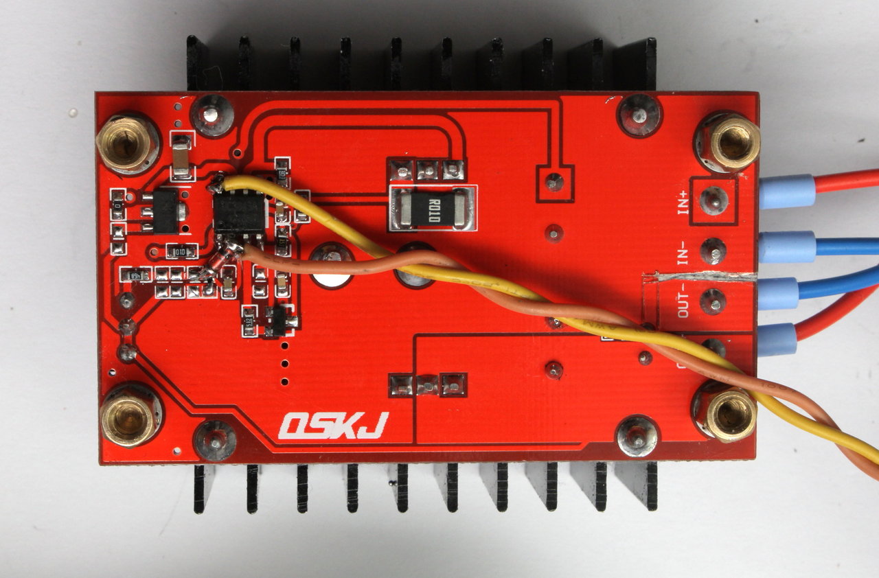
Inexpensive (currently €3.50 ¦ 19.05.2014) are available 150W Step-Up module, based on the PWM controller UC3843A with the following parameters:
- Input voltage: 10-32V
- Output voltage: 12-35V
- Input current: 10A (16A Max with extended cooling)
- Output power: 100W (150W Max with extended cooling)
- Efficiency: 94% (input 16V, output 19V 2.5A)
- Ausgangsspannungsripple: 2% max
- Load regulation: -0.5%
- Voltage regulation: -0.5%
- no short circuit and reverse polarity protection
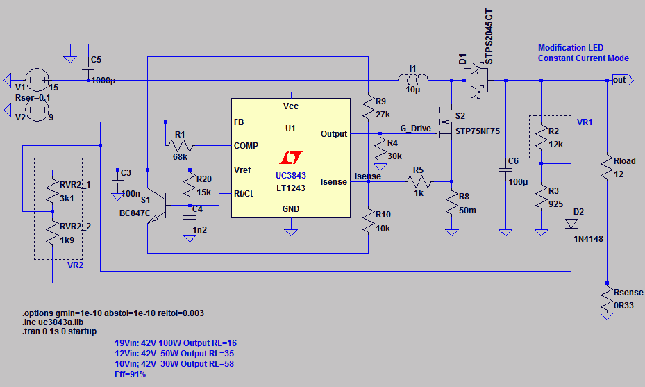
Als Leistungsschalter findet ein STP75NF75 Einsatz (75V 80A NMOS), Leistungsdiode ist STPS2045C (45V 30Arms Schottky). Ohne Austausch des Leistungsschalters und der Diode sind somit Ausgangsspannungen von maximal 45V möglich.
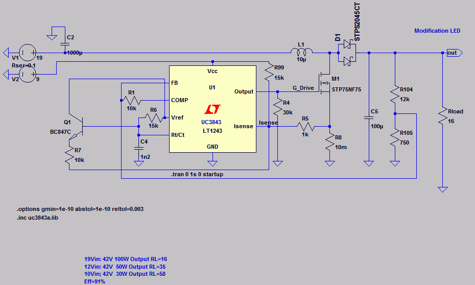
Following figure shows the original circuit:
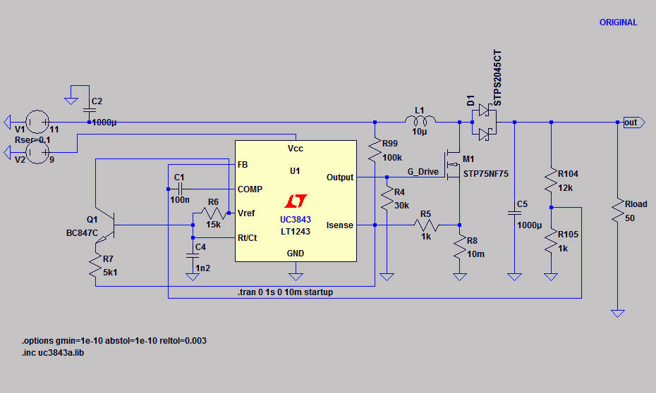
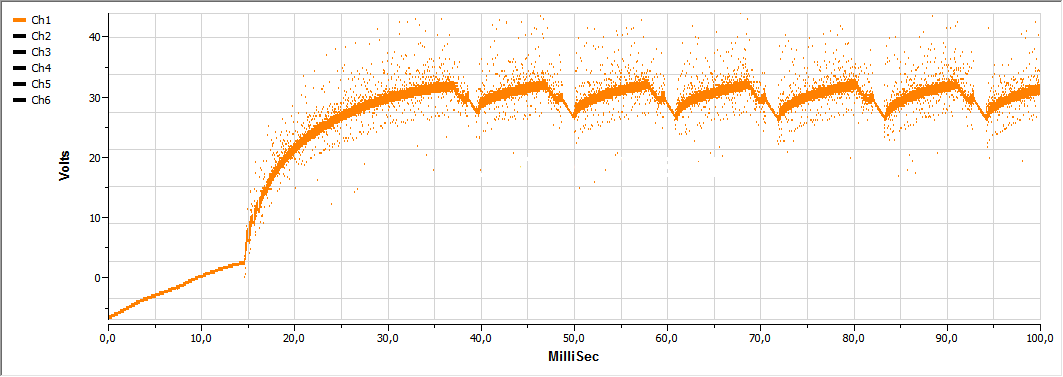
This has the disadvantage of being unstable in higher load ranges and/or translation ratio. At UIN = 12V4, Uout = 32V and Rload = 15R2 (Iout = 2A, pout = 67W) shows the measurement to the following of the unmodified circuit behavior (Orange = Vout, blue = VInduktor):

Modification
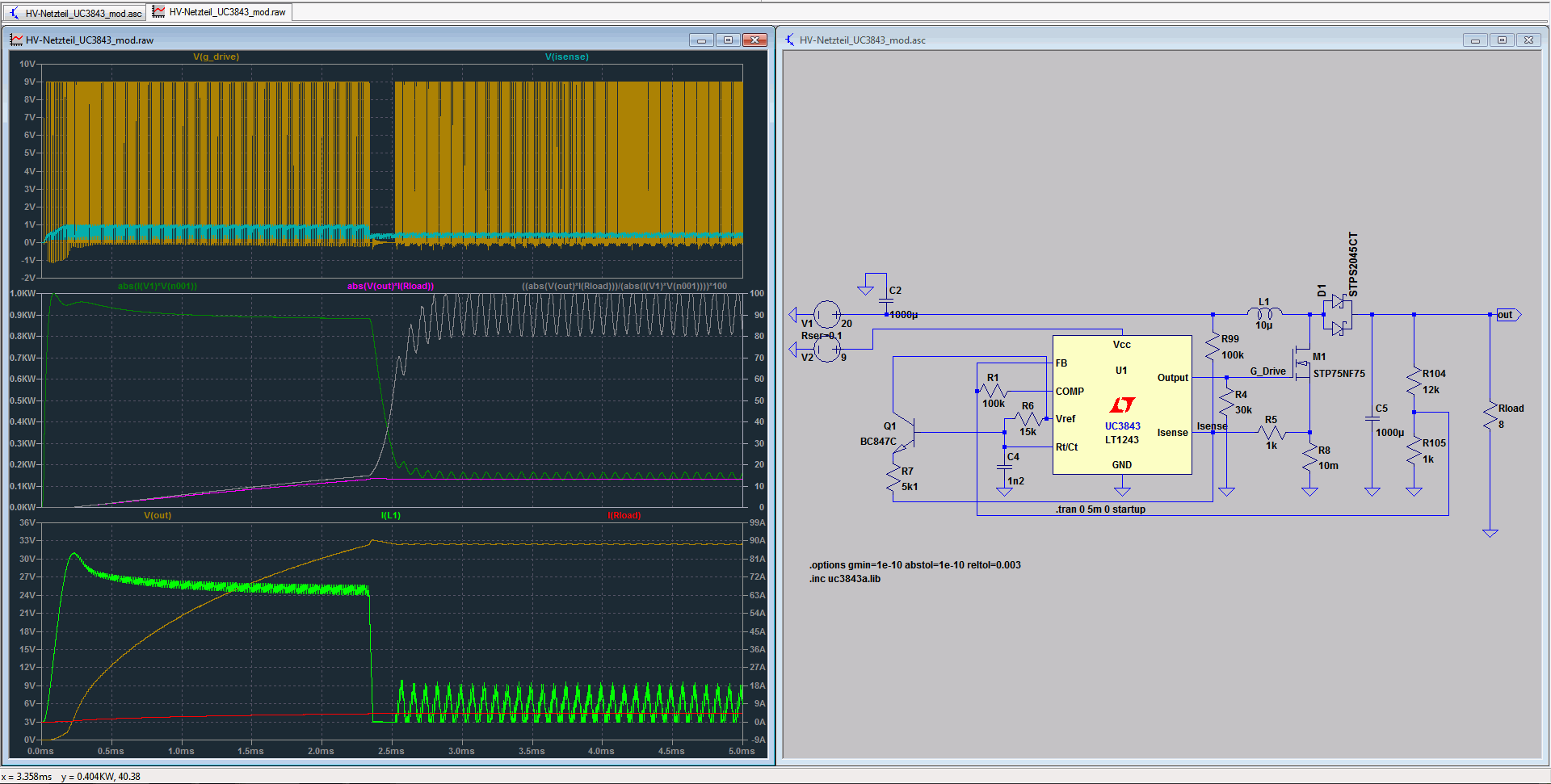
For subsequent simulation (original), C1 is replaced with a resistor (100 k). 20V input voltage, 32V output voltage (4A/120W) reveals the instability of the arrangement:
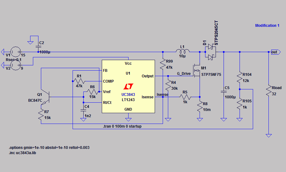
To stabilize are changed in the other R1 and R99 worth (modification 1).
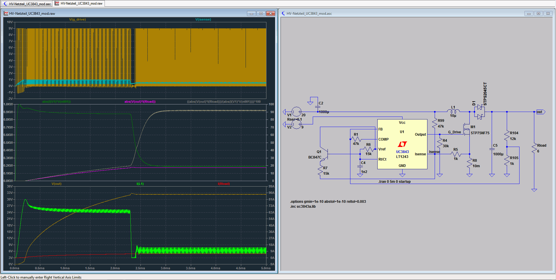
The example simulation to 20V input voltage, output voltage (5A/160W) 32V shows:
Current limitation
For use as a purely limited voltage LED driver the circuit can be modified, as shown below, continue. Be changed to the value R1/R7/R99, the connection of R99 is now on the 9V (7809). Note the minimum input voltage for different outputs.
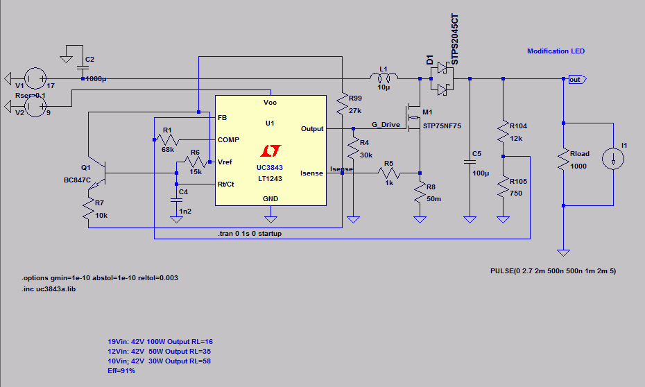
A modification is necessary for constant current mode as shown in the following figure. R9(R99) is equipped with 9 k 1 / 10 k to be provided. Furthermore a measuring shunt 0.33Ohm (load resistance), a standard diode (1N4148 or similar), as well as a 5kOhm potentiometer (10 speed potentiometer/trimmer preferred) needed. The shunt is inserted "low side" in the output circuit, the potentiometer accordingly connected to the shunt, VfB (Pin2), as well as the Vref (Pin8).

R2/R3 represent the (newly added) potentiometer, Rload the LED in the simulation. The open circuit voltage is adjusted with the already existing potentiometer, this shall be less than the voltage value of the output capacitor. For proper operation, it is essential that the output voltage (or voltage of the LED) at the nominal current is greater than the input voltage of the Step-Up Converter. The test setup is shown below. For higher currents, the value of the shunt is reduced to minimize voltage drop and power dissipation. The structure shown here has with 1A nominal power (LED) an efficiency of ~ 86%.

The circuit tag in the summary:
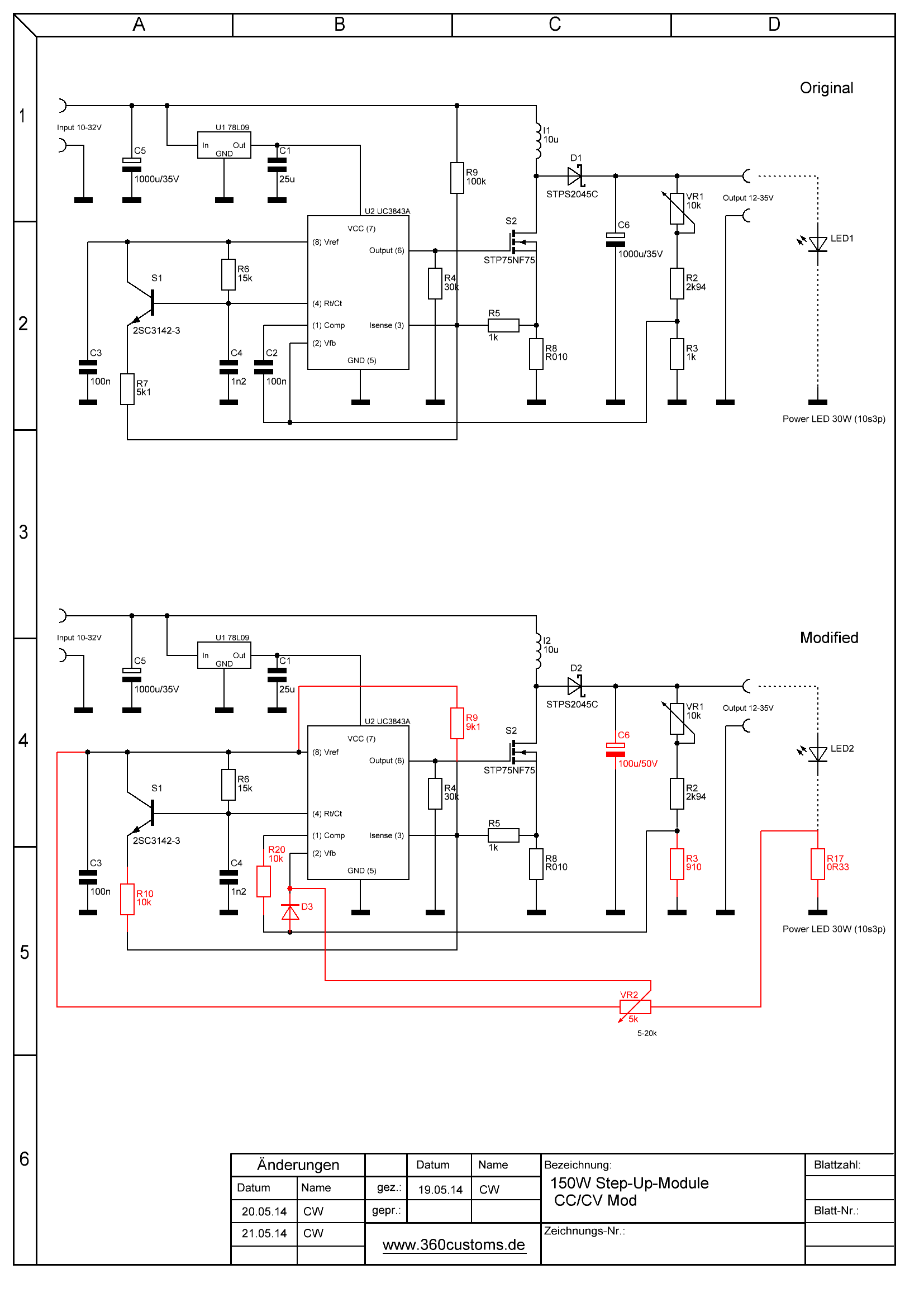 Because the circuit with R8 (measuring shunt 10 mohm) is a bit on the low end, it is, to replace it with 50mOhm. This results in a higher control loop stability, also the feedback (compensation) to be interpreted high-ohmig. The changes for constant voltage/constant current shown below:
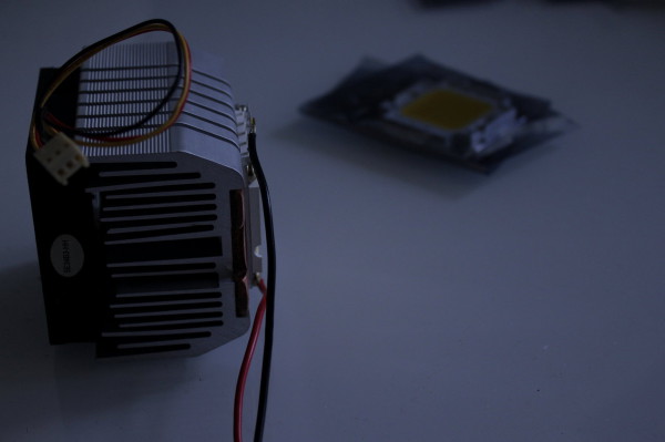
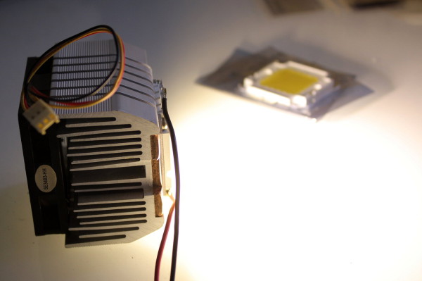
Finally some pictures of the color impression on each fixed white balance (daylight) / Aperture / Shutter speed (separately for both subjects):


Upgrade
For great Step-Up ratios, it has proven to replace the coil against models from Coilcraft. Without further alteration, 33uH work here without any significant heating - even at 12V-> 36V and 150W power consumption.
Coilcraft VER2923-333KL
Coilcraft AGP2923-333KL
If voltage ripple is not an issue,
could be used.
AGML battery charger
If you would like to know more, look in the D amp-Forum over.
LTSpice simulation: Download (zip)


Excellent work. I bought one of these and capacitor for only 35V drew my attention to find info about the IC used.
I used the board briefly with 3 cell Li-Po to power 50W LED (32-36V) and both MOSFET and 1000uF Cap were very hot.
I put your improvemnets into practice, but probably will have to mount MOSFET on larger heatsink and change 35V cap too.
Thanks
Hello,
nice design indeed, could you give a couple of tips how to apply the control function correctly in your design, for example apply the opto-coupling (fod817) & have possibility to switch ON/OFF the driver by MCU?!
Thanks an advance for reply,
Roman.
As the controller doesn’t feature an enable-pin nor have this functionality integrated anyway, i’d suggest an (isolated) high/low-side-switch in front or after the converter.
hi there… it is nice thread here…. but i am sorry my english is bad..
would you like to help me how to protect this driver to be saved? and not very hot?
i used this original circuit to drive 50 watt led, i set the VR at 32 volt… source input voltage to 12 volt battery 3A on my motor cycle… this circuit it so hot and was blown and also got smoke at IC UC3843 at least 15minutes while i driven the motorcycle..
please help me how to make this circuit work better and safer to drive 50Watt led on my motorcycle 12v battery 3A…
i’m waiting for your answer, email me please at hilmanropiudin@gmail.com
best regard
Brother, 50 watt LED should not be driven at 25. It should be 24 volt maximum at 2.5 amps. Better you use constant current at 2.5 amps.
Hi, thank you for sharing it. I wish to use a 100W LED rated at about 35V, using 12V-14V input. Is it possible with this circuit? Just a couple of questions more: it is possible to make it dimmable? Also, what are the power requirements for the resistors Rsense and R8? Thank you a lot for your answer.
Rsense would be 4W at 3.5A LED current – so you may use a smaller value and trim to the current with the pot. R8 is 1W.
Hi, thanks for this post!
Even if im a bit late these DC boosters are still the same and i learned a bit more on how they work 🙂
Can i ask what’s the meaning of R99 on this circuit? why would you need to give a constant bias to ISENSE? Also why do you use 9V for the voltage regulated one and the Vref for constant-current one?
thanks.
As far as i remember, the bias is needed to have better regulation when in current limit mode. It also helped on stability issues in the original schematics. The original is 100k 1k 10m here. It also is part of the slope compensation.
I need to modify this to a fixed output voltage of 36.4v and 1 A constant current. Would you have any advice for what component values to use to accomplish this?
Several parts need to get changed. You’ll have to add the current limit loop, change output filter caps for higher voltage rating (50V) and have the voltage limit resistance increased (before the voltage trimming pot)
Regards,
Christian
Thanks for a lot of very useful information, I have built a 100w led light powered by a 18v lion battery from one of my power tools used the information off youtube DIYPERKS for power LED light……I blew the module up after building it into its mesh case so you circuits have been helpful, i have ordered a couple of more modules to play around with.
I built the light as I needed a flood for use on forest and farm land that had a long switch on time from a 4500ah 18v battery
Regards steve
Hi 360Custom. My question is, why did you remove copper between in and out grounds? Thanks!
Thanks for your sharing.
Campos
This was meant for another current-sense-resistor – not needed in the end.
Btw. if you change the inductor for a Coilcraft VER2923 (10-33uH) the converter does the full 150W with ease, even big step-up-ratios of >1:3 (i.e. 10V -> 35V).
Regatta, Christian
Really appreciate your sharing, because I am working with some lights that I am doing for my son and for me to use them in photography. I knew that this boosters needed something, but I did not know what and how to improve it. I am waiting a few of them and when I get them and make the changes I will tell you how they did it. Another question. I am using an LED of 100 watts, the modification that you have here works OK with 100 W or I need to do an extra mods? Thanks and again, and have a great day and week!
Hi John,
it depends on your step-up-ratio. If you i.e. step up from 10V to 35V, you’ll noticethat the inductor will get very hot if it works at all. Changing the inductor for a Coilcraft VER2923 (33uH VER2923-333KL or AGP2923-333KL) works for me up to 150W. If you always going to run at high currents, the HA3588-BL might work as well (10uH). Higher current -> less inductance needed (but higher ripple).
Regards, Christian
Hello,
Thank you for this interesting designs, they offer a wonderful base for further projects.
A small discrepancy I noticed though:
Considering the Spice circuits to the constant current and the summary is marked in colour, diode D2/D3 is wired differently. The spice is right behind the potentiometer VR1 / R3 and influenced both FB direct, COMP via R1 and the VR2. The shimmery plan is the diode directly before FB, before VR2 come on in, and * behind * R1(R20) is to COMP.
It will vote because exists but the typical voltage drop of the diode, only a version, I suppose.
Is it correct to take the Spice version here?
Best regards!
Mike
Hi Mike,
Thanks for the comments. Both circuits are equivalent to on the circuit of R1 at COMP. Both will work – the SPICE circuit is preferable. (Theoretically push the diode to the voltage divider, then it will be shown)
Greeting Christian
Hello , congratulations on your posting.
I have convert identical. I want to use in electric motor 18 VDC x 8A through the 12 volt battery.
What change in this circuit that could help me.
Return wait .
Thank you/
18VDC * 8A 144VA - way = to much for the converter. You'd better got for a 600W converter that can be found on eBay at ~ $14.
Regards, Christian
Get them here: http://www.ebay.de/itm/310523503559