Signal / frequency / function generator 0.1Hz-200kHz (sine, square, and triangle)
Table of Contents
A simple (fully analog) frequency generator can be build by the help of a 4 channel op-amp ()LMH6644), 6 transistors and a few passive components. The symmetrical power supply ( /-5-12V) is done using either a transformer or a charge pump. (The circuit can be used as discrete replacement for MAX038, ICL8038, XR2206, IA338D )
Basic circuit
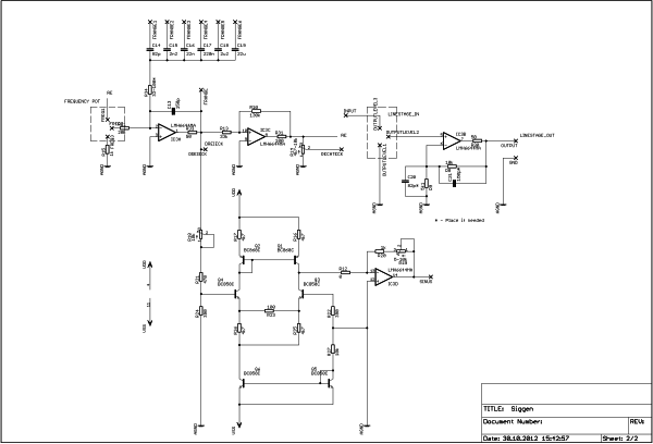
The circuit is based on a triangle/rectangle generator combination (IC3A IC3C). The frequency-range is given by the capacity values C14-C19 connected in the feedback, the exact frequency adjustment is done via the proportional feedback of the square wave signal back on the triangle generator.
Sinussynthetisator
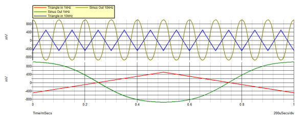
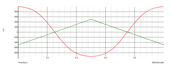
The sine wave signal is produced by a "Sinussynthetisator". At f = 1kHz, a distortion factor of about k = 0.5% is achieved. Basic element of the sine former is the differential amplifier (Q3 Q4), whose emitter currents are provided by the current-controlled current source (Q5 Q6). Since differential amplifiers without current feedback are only linear at low signal input voltage regarding differencies between input voltage and output current, there is a weak current feedback done via R13. Its value depends on the collector current of the transistor Q6.
It applies:
At this circuit sizing, the peak R21 symmetrical triangle voltage must meet the following condition:
For this purpose varying R18 until the THD sine output voltage reaches a minimum.
The transistors Q3 / Q4 operate the collector side of the current mirror Q1 / Q2, the collector current difference of the collector current sum of Q1 / Q3 corresponds, which flows into the inverting input of the operational amplifier IC3D and at the output provides a sinusoidal voltage whose amplitude is proportional to the product of amount of current sum and the sum of the resistors R19 / R20 is.
Sources:
Mikroelektronik in der Amateurpraxis 2 (1.Auflg. 1984); Militärverlag der DDR
Kühne/, C. : Einfaches Sinusfunktionsnetzwerk, radio fernsehen elektronik 31 (1982) Heft 10, Seite 662-663
Kühne/, C. : Begrenzer für Sinussynthetisatoren, radio fernsehen elektronik 28 (1979) Heft 7, Seite 431-433
AGML battery charger
The following diagram shows a simple linear power supply.
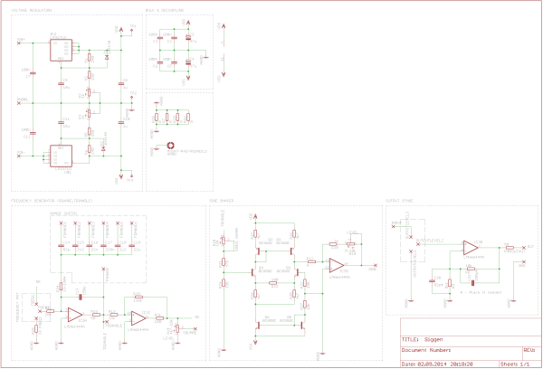
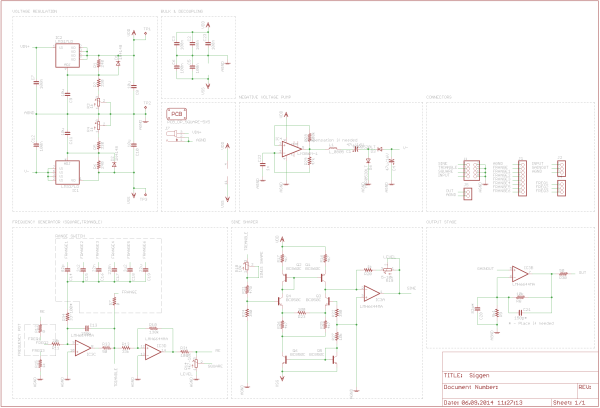
Combining both, the wiring diagram is given by:
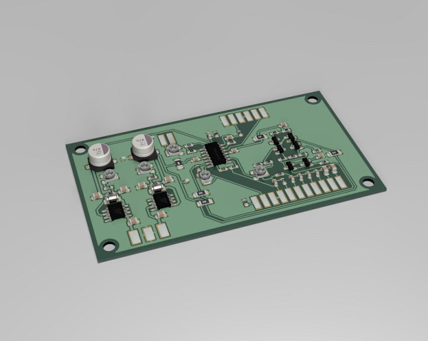
PCB type 1
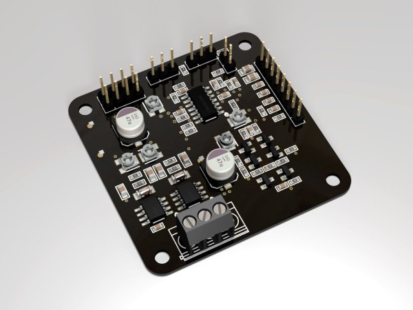
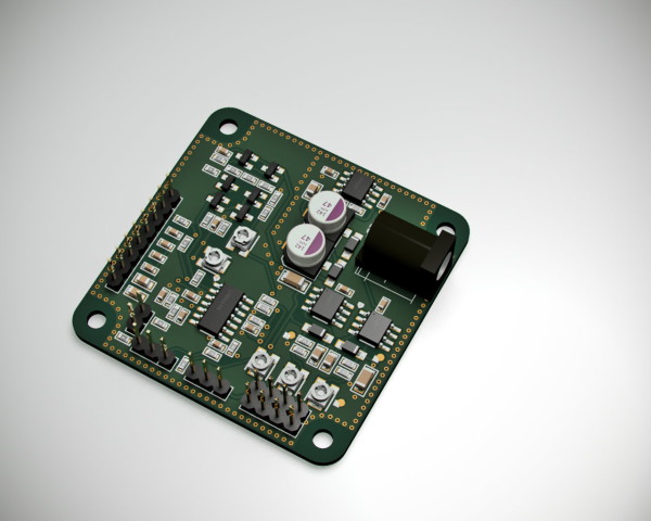
PCB version 2 at 50x50mm.
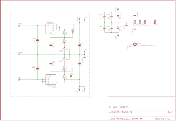
If you have not symmetrical power supply, the negative operating voltage can be generated, for example, with a charge pump - there are several possibilities.
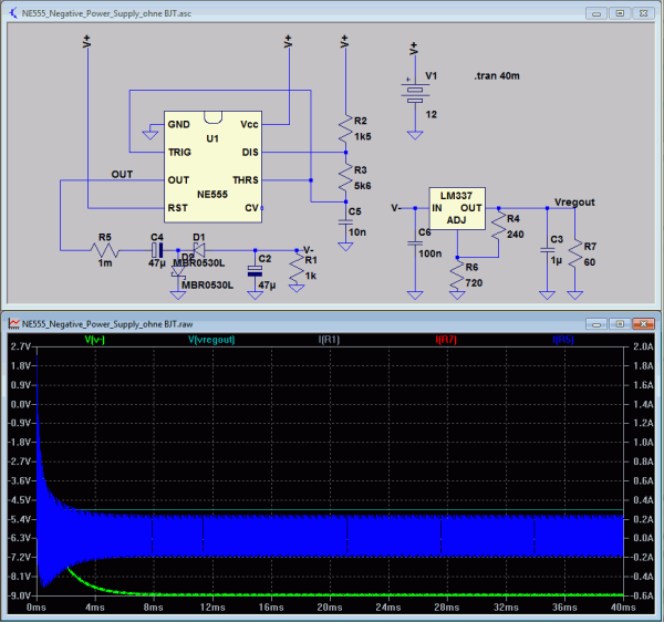
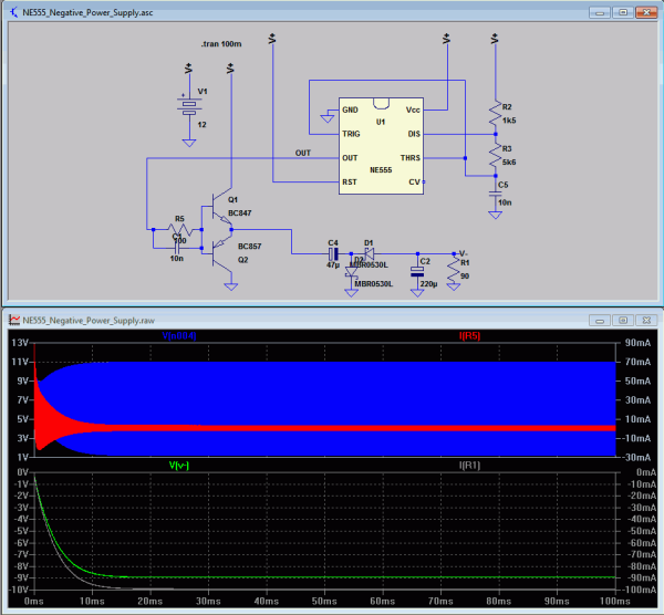
Timer 555 linear regulator LM337
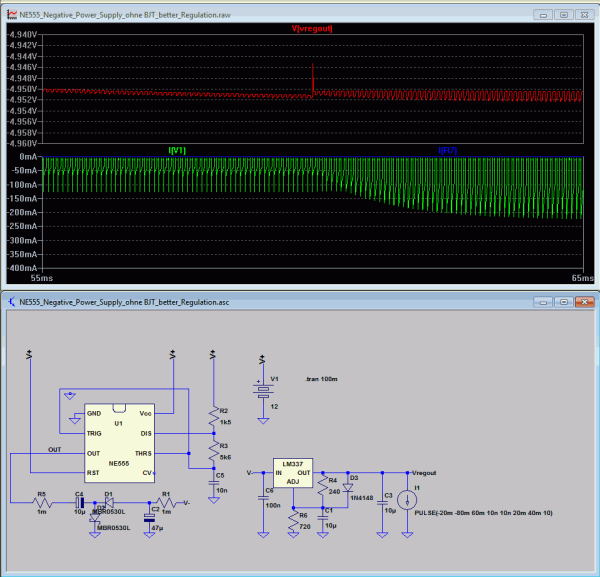
Below some considerations with 555 and LM337 as shunt regulator.
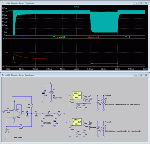
LM386 LM337
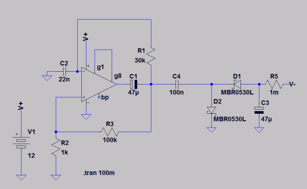
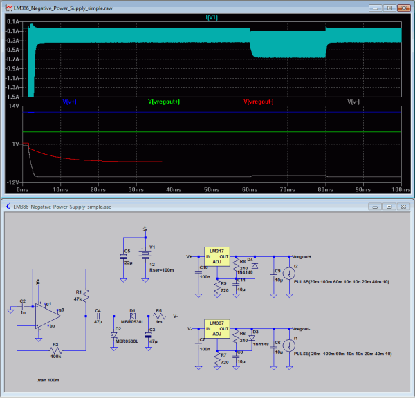
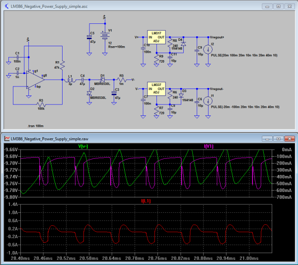
Alternatively to the timer 555, an LM386 are used in self-oscillating circuit, as shown in the following consideration.
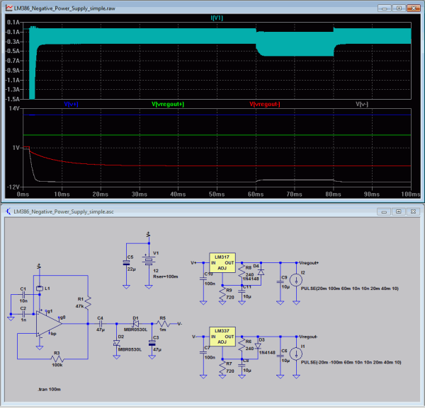
The input-side current peaks at load currents > = 100mA can be minimized by a circuit modification, as the following comparison shows. (R1/C1 released, R1 therefore, because of the LM386 is already internal base resistors)
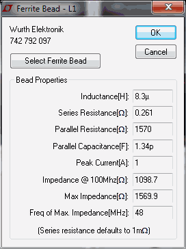
Through the use of an input-side inductor capacitor, the efficiency at light loads may slightly be improved (probably not relevant in practice) - at the expense of a larger voltage drop at higher loads.
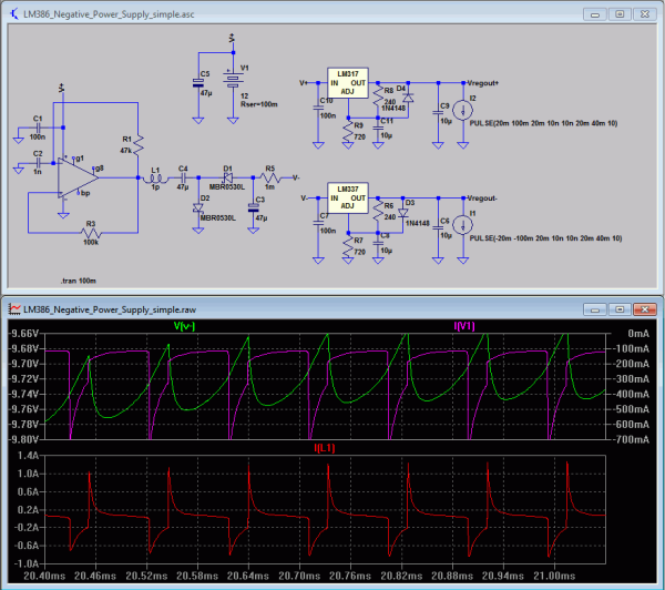
Finally, as the following comparison shows, current transients can be attenuated with a series inductance at the output of the inverter when needed. (Probably not relevant in practice)
Thus combined schematic results to:
Further discussion on stromrichter.org.


Hello!
Could you please give the PCB file signal generator?
Thank you!
Yes, no problem.
Hello,
Congratulations for the good function generator project.
It is possible to provide the PCB file for fabrication of the PCB?
Thank you very much!
Mauro