10/30/50/100W LED Applikation Treiber (UC3843A)
Table of Contents
Der Betrieb von Power-LEDs fordert Konstantstromquellen höherer Leistung. (>=1A).
Exemplarisch sei hier der Betrieb einer 30W LED an einem modifizierten Step-Up-Wandler (Boost) gezeigt.
Zur Verwendung steht eine 30W Leistungs-Led mit folgenden Parametern:
- Leistung: 30W
- Farbtemperatur: 3000-3500k
- Betriebsspannung: 30-38V
- Betriebsstrom: 1A
- Lichtstrom: 2600-2800 Lumen
- Lebensdauer: >50.000 Stunden
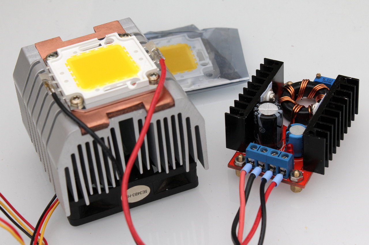
Am Labornetzteil stellt sich der Betriebsstrom von 1A bei ca. 38V ein.
Ist keine Konstantstromquelle verfügbar, kann die LED mit Unterspannung, bei geringen Lichtstromeinbußen, betrieben werden. Hierbei wird eine Spannung gewählt, bei dem der Strom 10% unter dem Betriebsstrom liegt (900mA). Es ist sicherzustellen, dass der Strom, verursacht durch thermischen Drift, den vom Hersteller angegeben Betriebsstrom nicht überschreitet.
Mit Hilfe eines Step-Up-Wandlers (Boost) lassen sich diese LEDs auch an Spannungsquellen betreiben, deren Ausgangsspannung <= der Betriebsspannung ist. (Bspw. Batterien, Akkus, Netzteile)
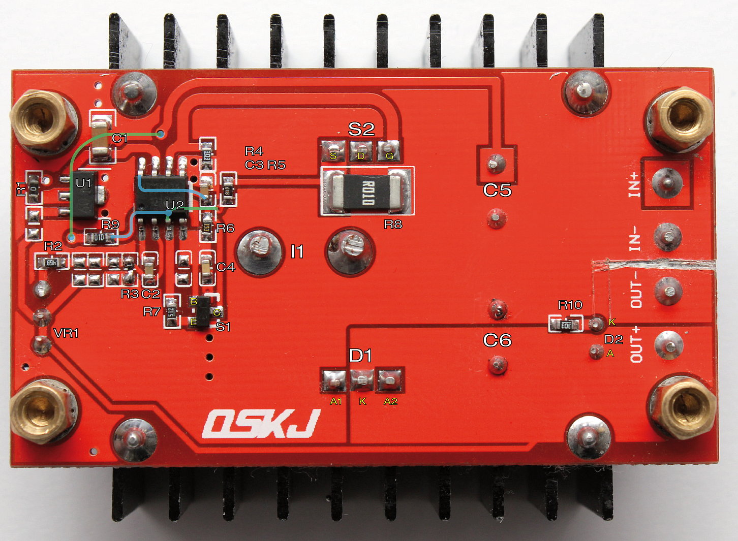
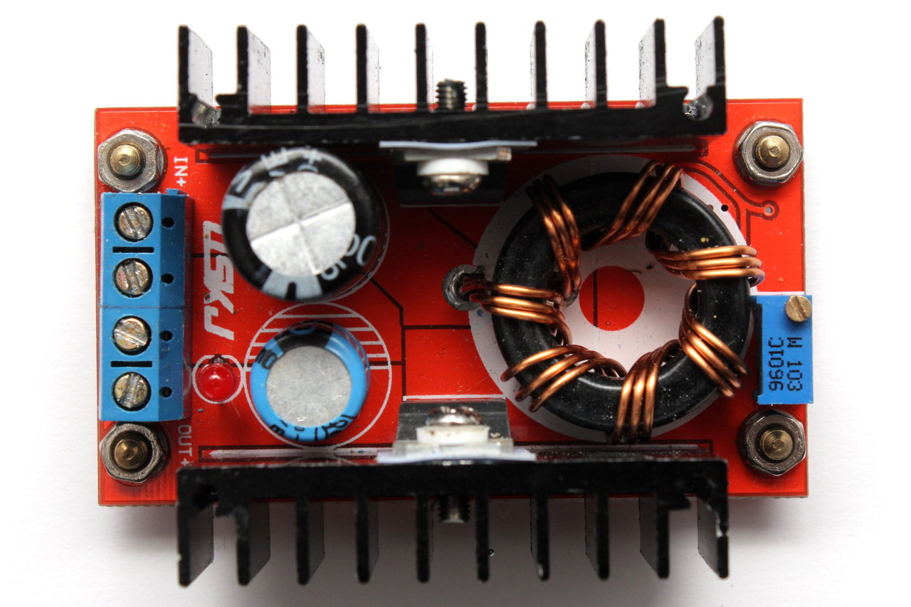
Kostengünstig (derzeit 3.50€ | 19.05.2014) verfügbar sind 150W Step-Up-Module, basierend auf dem PWM-Controller UC3843A mit folgenden Parametern:
- Eingangsspannung: 10-32V
- Ausgangsspannung: 12-35V
- Eingangstrom: 10A (16A max. mit erweiterer Kühlung)
- Ausgangsleistung: 100W (150W max. mit erweiterer Kühlung)
- Effizienz: 94% (Eingang 16V, Ausgang 19V 2.5A)
- Ausgangsspannungsripple: 2% max
- Lastregelung: - 0.5%
- Spannungsregelung: -0.5%
- kein Kurzschluss- und Verpolschutz
Als Leistungsschalter findet ein STP75NF75 Einsatz (75V 80A NMOS), Leistungsdiode ist STPS2045C (45V 30Arms Schottky). Ohne Austausch des Leistungsschalters und der Diode sind somit Ausgangsspannungen von maximal 45V möglich.
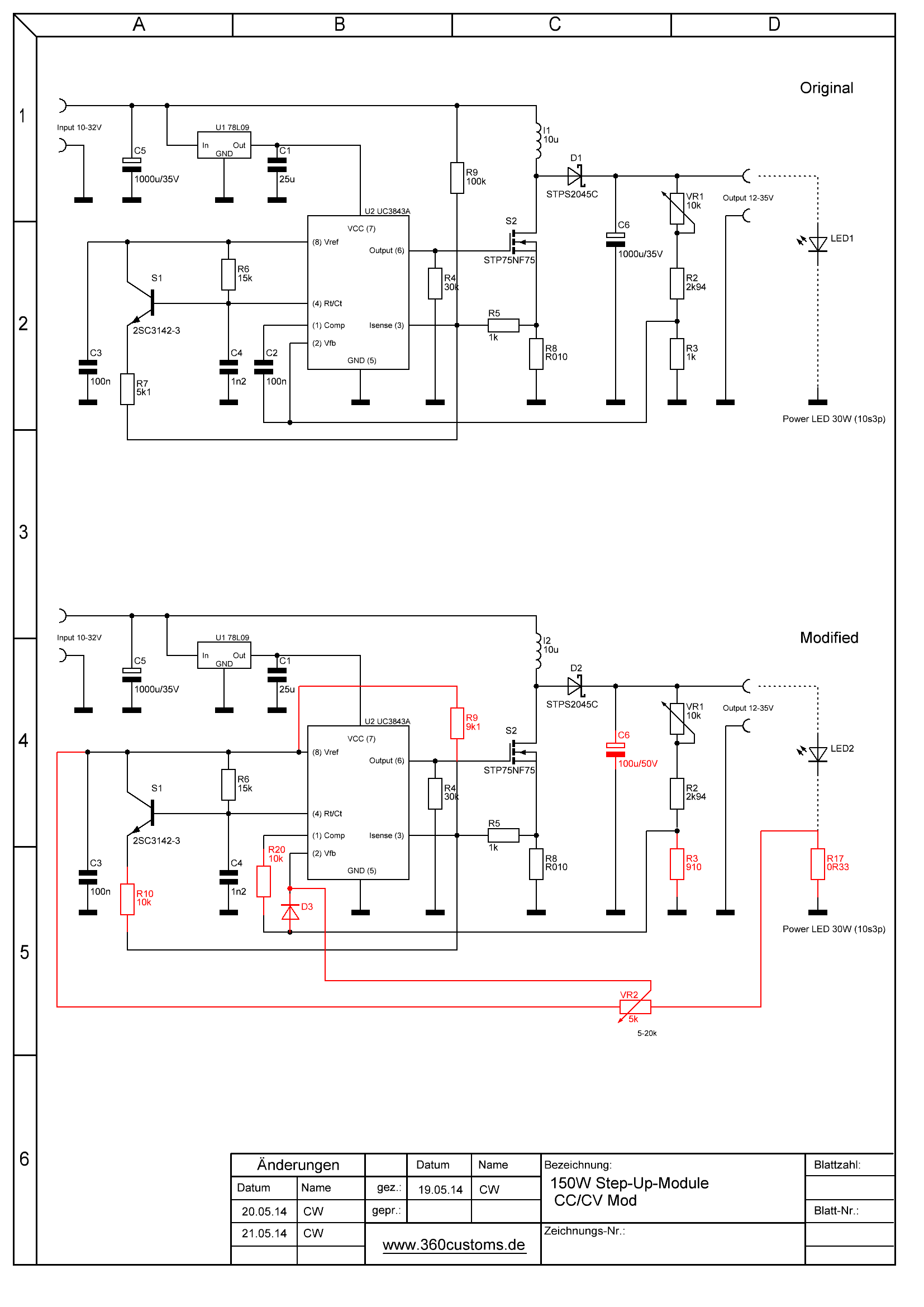
Die Originalschaltung zeigt folgende Abbildung:
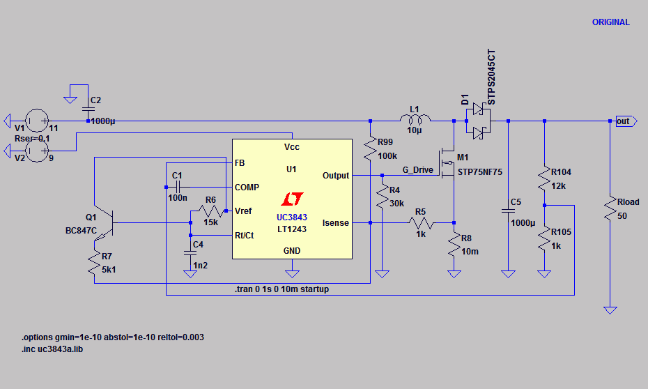
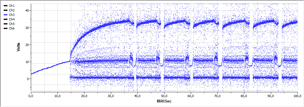
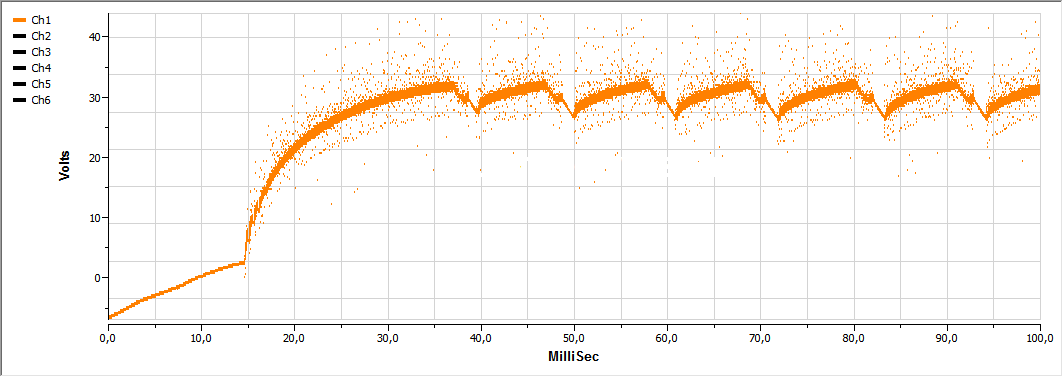
Diese hat den Nachteil, in höheren Lastbereichen und/oder Übersetzungsratio instabil zu sein. Bei Uin=12V4, Uout=32V und Rload=15R2 (Iout=2A, Pout=67W) zeigt die Messung an der unmodifizierten Schaltung folgendes Verhalten (Orange=Vout, Blau=VInduktor):
Modifikation
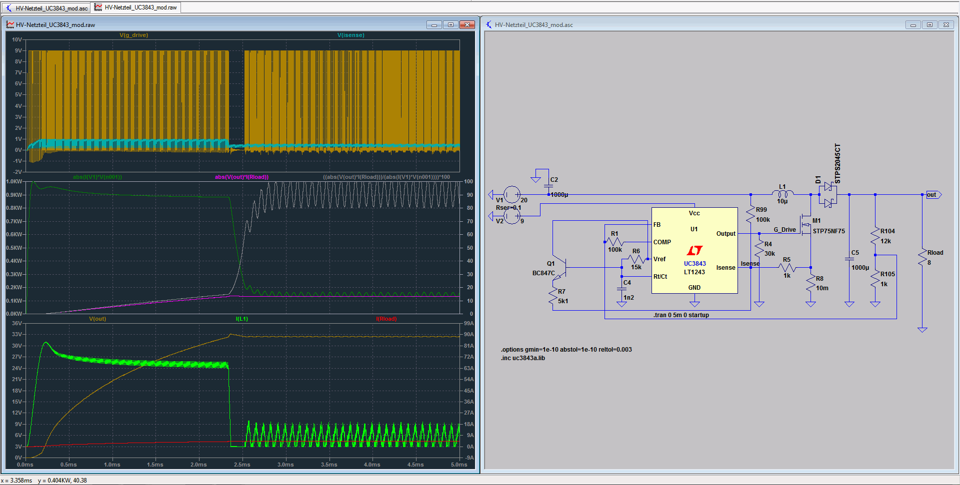
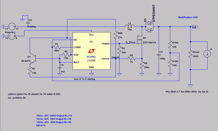
Für nachfolgende Simulation (Original) wird C1 durch einen Widerstand (100k) ersetzt. Bei 20V Eingangsspannung, 32V Ausgangsspannung (4A/120W) zeigt sich die Instabilität der Anordnung:
Zur Stabilisierung werden im weiteren R1 und R99 im Wert geändert (Modification 1).
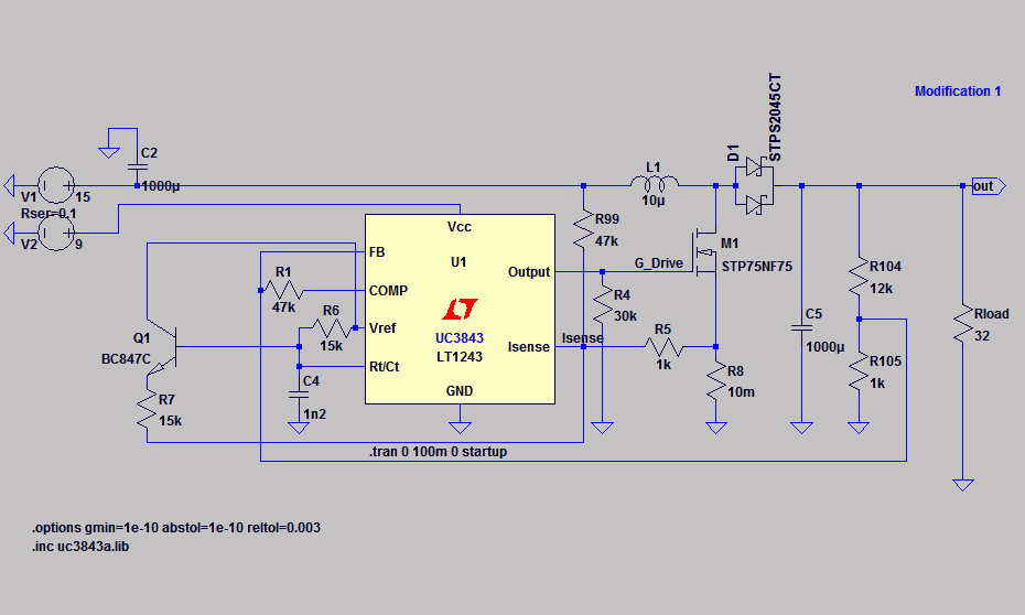
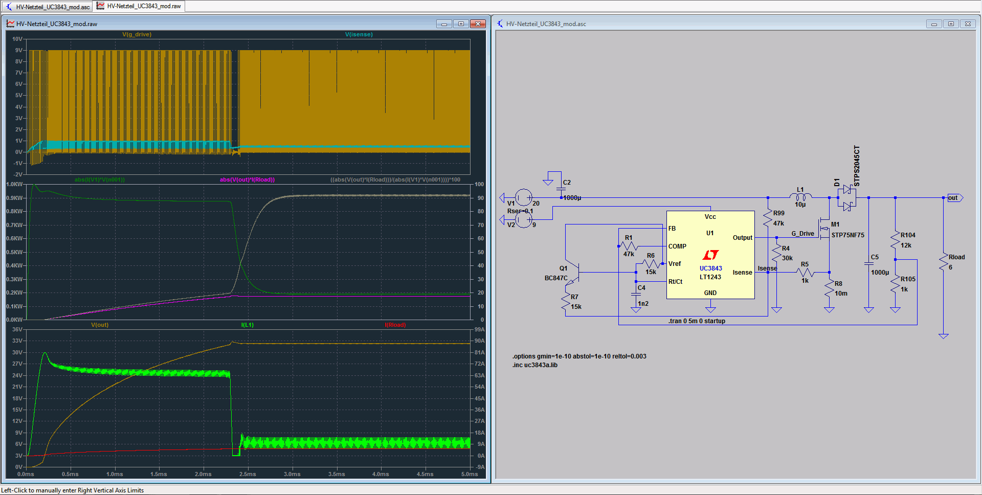
Die Beispielsimulation bei 20V Eingangsspannung, 32V Ausgangsspannung (5A/160W) zeigt:
Strombegrenzung
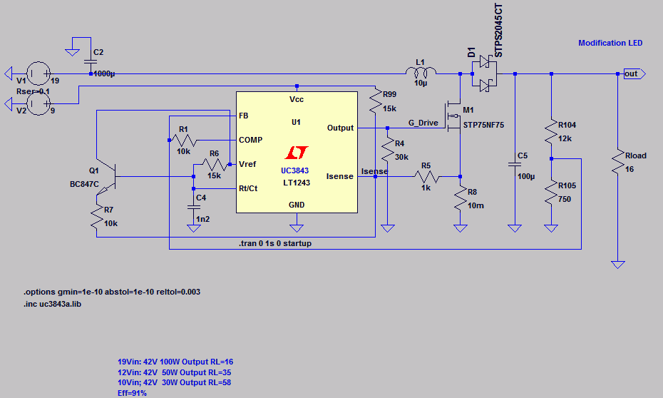
Zur Verwendung als rein spannungsbegrenzter LED-Treiber kann die Schaltung, wie nachfolgend gezeigt, weiter modifiziert werden. R1/R7/R99 werden im Wert geändert, die Anbindung von R99 ist nun am 9V (7809). Zu beachten ist die Mindesteingangspannung für verschiedene Ausgangsleistungen.
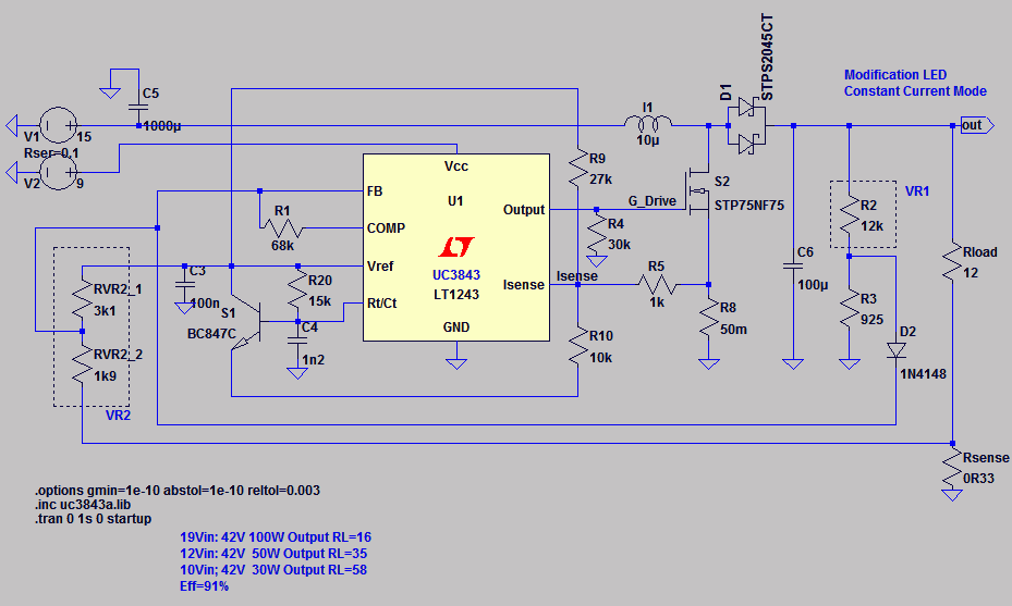
Für Konstantstrombetrieb ist eine Modifikation nach folgender Abbildung notwendig. R9(R99) ist mit 9k1/10k vorzusehen. Des Weiteren werden einen Messshunt 0.33Ohm (Lastwiderstand), eine Standarddiode (1N4148 o.ä.) sowie ein 5kOhm Potentiometer (bevorzugt 10-Gang-Poti/Trimmer) benötigt. Der Shunt wird “low-Side” in den Ausgangsstromkreis eingefügt, das Potentiometer entsprechend mit dem Shunt, Vfb (Pin2) sowie Vref (Pin8) verbunden.
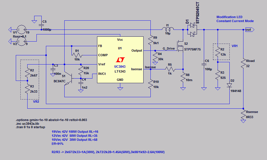
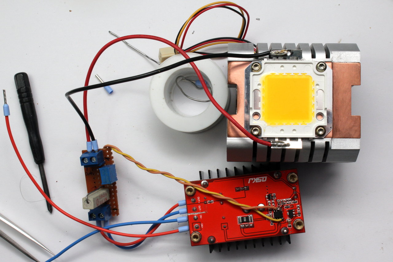
R2/R3 repräsentieren in der Simulation das (neu hinzugefügte) Potentiometer, Rload die LED. Die Leerlaufspannung wird mit dem bereits vorhandenen Potentiometer eingestellt, diese muss unter dem Spannungswert des Ausgangskondensators liegen. Für einen ordnungsgemäßen Betrieb ist es unabdingbar, dass die Ausgangspannung (respektive Flussspannung der LED) bei eingestelltem Nennstrom größer ist als die Eingangsspannung des Step-Up-Wandlers. Der Testaufbau ist nachfolgend dargestellt. Für höhere Ströme wird der Wert des Shunt verkleinert, um Spannungsabfall und Verlustleistung gering zu halten. Der hier gezeigte Aufbau hat bei 1A Nennstrom (LED) eine Effizienz von ~86%.
Der Schaltungsumbau in der Zusammenfassung:
 Da die Schaltung mit R8 (Messshunt 10mOhm) eine “heisse Kiste” ist, bietet es sich an, diesen mit 50mOhm zu ersetzen. Damit ergibt sich eine höhere Regelkreisstabilität, auch kann die Rückkopplung (Kompensation) hochohmiger ausgelegt werden. Nachfolgend gezeigt die Änderungen für Konstantspannung/Konstantstrom:
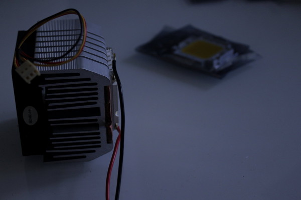
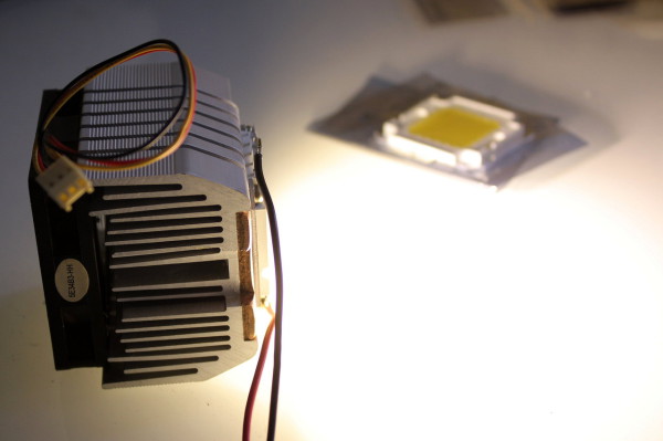
Abschliessend einige Bilder zum Farbeindruck bei jeweils festem Weissabgleich (Tageslicht)/Blende/Belichtungszeit (getrennt für beide Motive):


Upgrade
Für große Step-Up-Verhältnisse hat es sich bewährt, die Spule gegen Modelle von Coilcraft auszutauschen. Ohne weiteren Umbau funktionieren hierbei 33uH problemlos ohne nennenswerte Erwärmung – selbst bei 12V -> 36V und 150W Leistungsentnahme.
Coilcraft VER2923-333KL
Coilcraft AGP2923-333KL
Wenn Ripple kein Problem ist kann auch
verwandt werden.
TPA3116r…
Wer mehr erfahren möchte, schaut im D-Amp-Forum vorbei.
LTSpice Simulation: Download (Zip)


Excelente trabajo. Compré uno de estos y el condensador por solo 35V llamó mi atención para encontrar información sobre el IC utilizado.
Usé la placa brevemente con Li-Po de 3 celdas para alimentar un LED de 50 W (32-36 V) y tanto MOSFET como 1000uF Cap estaban muy calientes.
Puse en práctica sus mejoras de red, pero probablemente tendré que montar MOSFET en un disipador térmico más grande y cambiar también la tapa de 35V.
Thanks
Hola,
diseño agradable de hecho, podría dar un par de consejos cómo aplicar la función de control correctamente en su diseño, por ejemplo, aplicar el opto-acoplamiento (fod817) y tienen posibilidad de activar / desactivar el controlador MCU ?!
Gracias un avance para la respuesta,
Romano.
A medida que el controlador no cuentan con un patillas permitir que ni tienen esta funcionalidad integrada de todos modos, me gustaría sugerir un (aislado) de alto a bajo botón lateral / delante o después del convertidor.
hi there… it is nice thread here…. but i am sorry my english is bad..
would you like to help me how to protect this driver to be saved? and not very hot?
i used this original circuit to drive 50 watt led, i set the VR at 32 volt… source input voltage to 12 volt battery 3A on my motor cycle… this circuit it so hot and was blown and also got smoke at IC UC3843 at least 15minutes while i driven the motorcycle..
please help me how to make this circuit work better and safer to drive 50Watt led on my motorcycle 12v battery 3A…
i’m waiting for your answer, email me please at hilmanropiudin@gmail.com
best regard
Brother, el LED de 50 vatios no debe funcionar a 25. Debe tener un máximo de 24 voltios a 2.5 amperios. Mejor usa corriente constante a 2.5 amperios.
Hi, thank you for sharing it. I wish to use a 100W LED rated at about 35V, using 12V-14V input. Is it possible with this circuit? Just a couple of questions more: it is possible to make it dimmable? Also, what are the power requirements for the resistors Rsense and R8? Thank you a lot for your answer.
Rsense would be 4W at 3.5A LED current – so you may use a smaller value and trim to the current with the pot. R8 is 1W.
Hi, thanks for this post!
Incluso si soy un poco tarde estos propulsores DC siguen siendo los mismos y aprendí un poco más sobre cómo funcionan 🙂
¿Puedo preguntar cuál es el significado de R99 en este circuito? ¿Por qué necesitaría para dar una polarización constante a ISENSE? Además, ¿por qué se utiliza 9V para la tensión regulada uno y el Vref por una corriente constante?
Gracias.
As far as i remember, the bias is needed to have better regulation when in current limit mode. It also helped on stability issues in the original schematics. The original is 100k 1k 10m here. It also is part of the slope compensation.
I need to modify this to a fixed output voltage of 36.4v and 1 A constant current. Would you have any advice for what component values to use to accomplish this?
Several parts need to get changed. You’ll have to add the current limit loop, change output filter caps for higher voltage rating (50V) and have the voltage limit resistance increased (before the voltage trimming pot)
Saludos,
Christian
Thanks for a lot of very useful information, I have built a 100w led light powered by a 18v lion battery from one of my power tools used the information off youtube DIYPERKS for power LED light……I blew the module up after building it into its mesh case so you circuits have been helpful, i have ordered a couple of more modules to play around with.
I built the light as I needed a flood for use on forest and farm land that had a long switch on time from a 4500ah 18v battery
Regards steve
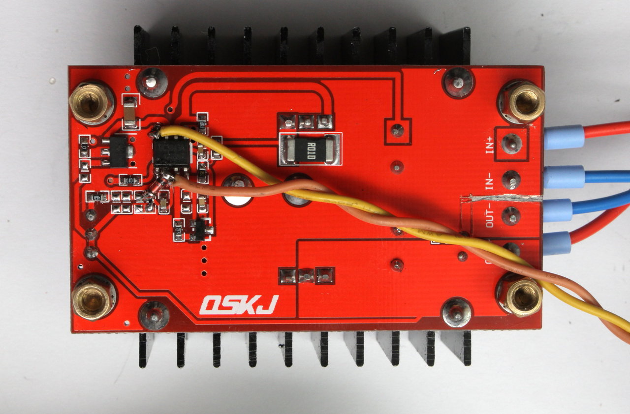
Hi 360Custom. My question is, why did you remove copper between in and out grounds? Thanks!
Thanks for your sharing.
Campos
This was meant for another current-sense-resistor – not needed in the end.
Btw. if you change the inductor for a Coilcraft VER2923 (10-33uH) the converter does the full 150W with ease, even big step-up-ratios of >1:3 (i.e. 10V -> 35V).
Regatta, Christian
Really appreciate your sharing, because I am working with some lights that I am doing for my son and for me to use them in photography. I knew that this boosters needed something, but I did not know what and how to improve it. I am waiting a few of them and when I get them and make the changes I will tell you how they did it. Another question. I am using an LED of 100 watts, the modification that you have here works OK with 100 W or I need to do an extra mods? Thanks and again, and have a great day and week!
Hay Juan,
it depends on your step-up-ratio. If you i.e. step up from 10V to 35V, you’ll noticethat the inductor will get very hot if it works at all. Changing the inductor for a Coilcraft VER2923 (33uH VER2923-333KL or AGP2923-333KL) works for me up to 150W. If you always going to run at high currents, the HA3588-BL might work as well (10uH). Higher current -> less inductance needed (but higher ripple).
Regards, Christian
Hola,
vielen Dank für diese interessanten Ausführungen, sie bieten eine wunderbare Basis für weitere Projekte!
Mir fiel allerdings eine kleine Diskrepanz auf:
Betrachtet man die Spice-Schaltungen zum Konstantstrom und die Zusammenfassung, in der farblich markiert wurde, dann ist Diode D2/D3 unterschiedlich verschaltet. Im Spice liegt sie gleich hinter dem Spannungsteiler VR1 / R3 und beeinflußt sowohl FB direkt, COMP über R1 und den VR2. Im colorierten Plan liegt die Diode dagegen direkt vor FB, davor kommt VR2 rein, und *dahinter* liegt R1(R20) zu COMP.
Davon dürfte, da an der Diode doch der typische Spannungsabfall vorliegt, nur eine Fassung stimmen, nehme ich an.
Ist es korrekt, hier die Spice-Fassung zu nehmen?
Besten Gruß!
Mike
Hola Mike,
danke für die Anmerkungen. Beide Schaltungen sind equivalent bis auf die Beschaltung von R1 an COMP. Beides wird funktionieren – die SPICE-Schaltung ist zu bevorzugen. (Gedanklich die Diode zum Spannungsteiler schieben, dann wird es ersichtlich)
Gruß Christian
Hello , congratulations on your posting.
I have convert identical. I want to use in electric motor 18 VDC x 8A through the 12 volt battery.
What change in this circuit that could help me.
Return wait .
Thank you/
18VDC*8A = 144VA – way to much for the converter. You’d better got for a 600W converter that can be found on Ebay at ~$14.
Regards, Christian
Get them here: http://www.ebay.de/itm/310523503559